Modern, high-performance pixel control for Cortex-M
A highly optimized Art-Net and sACN pixel controller for GD32 Cortex-ARM microcontrollers,
built around a Timer → DMA → GPIO architecture for
deterministic timing, minimal CPU overhead, and maximum output efficiency.
This design uses the hardware exactly where Cortex-ARM performs best:
timers for precise scheduling, DMA for data movement, and GPIO for direct waveform generation.
Key features:
- No artificial FPS limit beyond what is imposed by the selected pixel chip protocol.
- Full Art-Net 4 implementation, including ArtTrigger for running test patterns.
- Full sACN E1.31 implementation.
- Discovery and network configuration using RDMNet LLRP only.
- Configuration management with HTTP/JSON, including discovery support.
- TFTP server support for uploading new firmware.
Support for:
- RTZ protocol pixels, including predefined
chip types such as WS2812B. When different timing is needed, it can
be configured using custom low-code and high-code values.
- Clock-based protocol pixels: APA102, SK9822 and P9813.
Quick links:
Timer → DMA → GPIO
The output engine uses two timers in master-slave mode.
The master generates the DMA requests and the slave acts as the pixel buffer counter.
There is just one interrupt for the transfer lifecycle.
This makes the design exceptionally efficient for Cortex-M, because the waveform generation is handled by hardware rather than software polling or tight interrupt loops.
Why this architecture is so effective on Cortex-ARM
- Precise timing is generated by the timer hardware.
- DMA writes directly to the GPIO set/reset registers.
- CPU overhead stays low during pixel output.
- Interrupt pressure is minimized to a single interrupt for the transfer process.
- Scaling across multiple outputs becomes practical without compromising timing integrity.
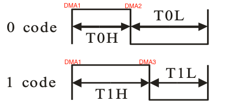
RTZ protocol DMA requests
For RTZ protocol pixels there are three DMA requests:
- Always the HIGH output.
- The LOW output for a 0 code.
- Always the LOW output after T1H.
|
 |
Timers used
| 2 |
Master → TIMER2_TRGO |
| 3 |
Slave → ITI2 |
DMA channels used
| MCU Family |
|
Channnel 0 |
Channnel 1 |
Channnel 2 |
Channnel 3 |
Channnel 4 |
Channnel 5 |
Channnel 6 |
Channnel 7 |
| GD32F20x |
DMA 0 |
|
TIMER2_CH2 |
TIMER2_CH3 |
|
|
TIMER2_CH0 |
|
|
| DMA 1 |
|
|
|
|
|
|
|
|
| GD32F4xx |
DMA 0 |
|
|
TIMER2_CH3 |
|
TIMER2_CH0 |
|
|
TIMER2_CH2 |
| DMA 1 |
|
|
|
|
|
|
|
|
SPI/I2S
As the SPI speed cannot be specified exaclty, the I2S peripheral is used instead.
SPI speed =
I2S bitrate = Audio sample rate * number of
bits per channel * number of channels. Therefore, the Audio sample
rate = SPI speed / 16 / 2. For the WS2812B type protocol, the SPI
speed must be (close to) 6.4Mhz.
Clock tree
| MCU |
CK_SYS |
CK_I2S |
| GD32F103RC |
108MHz |
108MHz |
| GD32F303RC |
120MHz |
120MHz |
| MCU |
CK_SYS |
HXTAL |
PREDV1 |
PLL2MF |
CK_PLL2 |
x2 |
CK_I2S |
| GD32F107RC |
- |
25MHz |
/5 |
x16 |
80Mhz |
√ |
160Mhz |
| GD32F207RG |
- |
25MHz |
/5 |
x16 |
80Mhz |
√ |
160Mhz |
| GD32F207VC |
- |
25MHz |
/5 |
x16 |
80Mhz |
√ |
160Mhz |
I2S prescaler Configuration
- Frame format: DT16B CH16B
- Number of bit per channel: 16
- Number of channels: 2
- Audio sample rate: 200kHz = 6400000 Hz / 16 / 2
- MCK out: Disable
I2S bitrate = CK_I2S / (DIV * 2 + OF)
| MCU |
CK_I2S |
DIV |
OF |
I2S bitrate |
| GD32F103RC |
108MHz |
8 |
1 |
6.352.941 |
| GD32F107RC |
160Mhz |
12 |
1 |
6.400.000 |
| GD32F207RG |
160Mhz |
12 |
1 |
6.400.000 |
| GD32F207VC |
160Mhz |
12 |
1 |
6.400.000 |
| GD32F303RC |
120MHz |
9 |
1 |
6.315.790 |
Development boards